A2L refrigerants didn’t remove Variable Refrigerant Flow (VRF) as an equipment option in hotels and multifamily buildings.
But they did change one of the first refrigerant safety checks engineers perform.
Instead of comparing total system charge to the smallest room, engineers now have to evaluate how much refrigerant could be released into the space.
That includes:
- The actual layout
- The smallest occupied spaces
- What qualifies as a connected space
- The amount of refrigerant that could be released into the room
It’s no longer just about ASHRAE 15 and ASHRAE 34.
Local code adoption, UL 60335-2-40, and how those standards are currently interpreted influence whether the design is effective.
This article highlights key insights shared by Chris Bellshaw of Daikin Comfort Technologies North America, Inc., on how A2L is changing early VRF design in multifamily and hospitality applications.
“A2L didn’t make VRF unworkable. It made simple early design checks unworkable.”
Chris Bellshaw, VP of Commercial Strategy and Business Development for Daikin Comfort Technologies North America, Inc.
Start with a VRF Layout vs. a Refrigerant Check
A refrigerant safety review starts with a layout. Locate indoor and outdoor units, estimate piping paths, identify branch or changeover box locations, and define the occupied and enclosed spaces that shape the next steps.
VRF System Layout 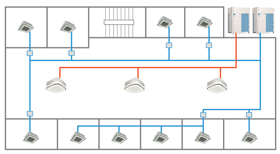
Example VRF system layout showing outdoor units, refrigerant piping network, and indoor units serving multiple spaces. A preliminary layout helps evaluate refrigerant distribution, room conditions, and areas that may need closer review. Source: Daikin Comfort Technologies North America, Inc.
In the layout, identify:
- Indoor unit types and locations
- Outdoor unit selection
- Approximate piping lengths
- Branch or changeover box locations
- A first-pass refrigerant charge estimate
- Enclosed and occupied spaces that need review
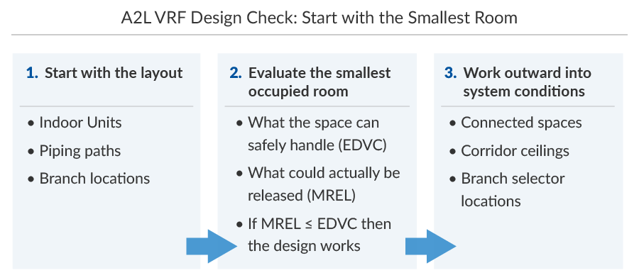
Once the layout is ready, the next step is to evaluate the Effective Dispersal Volume Charge (EDVC), Maximum Releasable Refrigerant Charge (MREL), connected spaces, and corridor conditions in the right order.
A typical design sequence looks like this:
- Lay out the system
- Identify occupied and enclosed spaces (start with the smallest room)
- Calculate the EDVC
- Calculate the MREL
- Then evaluate connected spaces and corridor conditions
How to Evaluate VRF Refrigerant Charge Limits
Now verify the system complies with the refrigerant safety limits defined in ASHRAE 15.
ASHRAE 15 now allows mitigation controls that can limit how much refrigerant is released into the space, which directly affects how MREL is evaluated.
Step 1: Calculate the effective dispersal volume charge (EDVC)
The EDVC calculation determines how much refrigerant can safely disperse within an occupied or connected space.
Spaces Evaluated for Refrigerant Safety
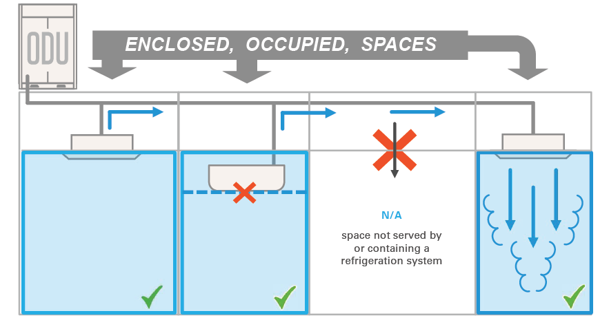
Only enclosed, occupied spaces served by the VRF system are evaluated when determining refrigerant safety limits. Spaces that are not conditioned or do not contain refrigerant piping are typically excluded. Source: Daikin Comfort Technologies North America, Inc.
Effective Dispersal Volume Charge (EDVC) formula:
EDVC = Veff × LFL × CF × Focc
- Veff = effective dispersal volume of the space
- LFL = lower flammability limit of the refrigerant
- CF = concentration factor
- Focc = occupancy adjustment factor
This means the allowable refrigerant charge is based on the actual volume of the space being evaluated.
- A single room
- Multiple connected rooms
- Corridor ceiling plenum
- Another enclosed zone connected by airflow
Identifying the smallest occupied space early in design is important.
Step 2: Calculate the maximum releasable refrigerant charge (MREL)
MREL represents the portion of refrigerant that could enter a space during a leak before mitigation control takes effect.
The MREL calculation typically includes:
- Refrigerant in downstream piping
- Refrigerant inside the indoor unit heat exchanger
- Refrigerant released before safety shutoff valves close
- Piping length and diameter near the leak location
Maximum Releasable Refrigerant Charge (MREL) formula:
Refrigerant contained in the indoor unit coil and downstream piping up to the shutoff valve
+
Additional refrigerant released during the shutoff valve closure delay
*In many VRF design examples, the valve-closure release is approximated at about 0.279 lb per SSOV, depending on system assumptions.
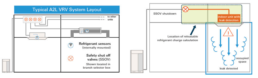
A2L VRF design focuses on releasable charge, not total system charge. Integrated leak detection and safety shutoff valves limit how much refrigerant can enter an occupied space, allowing engineers to evaluate compliance based on MREL versus EDVC. Source: Daikin Comfort Technologies North America, Inc.
In modern A2L VRF design, mitigation controls such as refrigerant sensors and safety shutoff valves can significantly reduce the amount of refrigerant that could enter a space.
That’s why MREL is often much smaller than the total system charge.
Step 3: Compare MREL to EDVC
As a final confirmation, compare MREL to EDVC.
If MREL ≤ EDVC = the system complies
If MREL > EDVC = mitigation or redesign is required
When the releasable charge exceeds the allowable dispersal volume, engineers typically resolve the issue by adjusting the design. Options include:
- Relocating branch selector boxes
- Reducing piping volume in the evaluated space
- Using connected-space calculations
- Adding mitigation controls such as leak detection or shutoff valves
Once that relationship is verified, start evaluating small rooms, connected spaces, and corridor ceiling conditions throughout the system.
How to Evaluate Small Rooms in A2L VRF Systems
Small rooms are still the first stress test in A2L VRF design because they often determine whether a system complies with refrigerant safety limits.
Small hotel and apartment room example
Consider a room that is 112 square feet with an 8.5-foot ceiling.
The maximum amount of refrigerant that could be released into that room is just over 9 pounds. At the indoor unit branch, assuming long piping, the maximum releasable charge is much lower at approximately 2.78 pounds.
In this case, most of the releasable charge comes from the piping, not the indoor unit. That is why piping length and branch location directly affect the calculation.
Do Bathrooms Count Toward VRF Room Volume?
Bathrooms only count if they function as a connected space.
If the bathroom has a closable door and no meaningful airflow path (no transfer grille or sufficient door undercut), it should not be included.
If there is a clear airflow path, it can be included.
Do not include the bathroom just to increase allowable volume. Include it only when the connected-space logic is real and defensible.
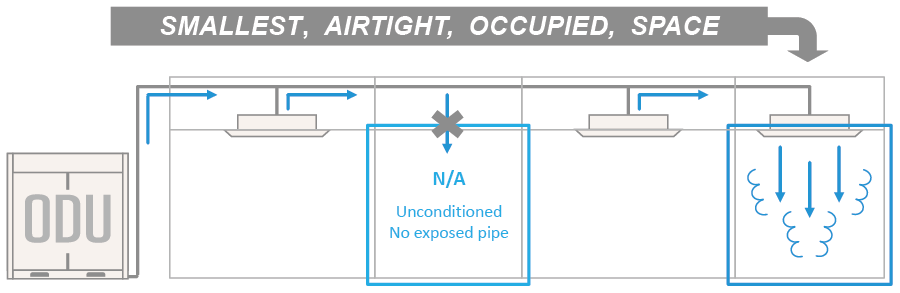
In A2L VRF design, evaluate the smallest enclosed space served by the system when checking refrigerant charge limits. Source: Daikin Comfort Technologies North America, Inc.
Corridor Ceilings and Branch Selector Boxes in VRF Design
When refrigerant piping or branch selector boxes are located above corridor ceilings, that plenum may become the space used for refrigerant dispersion calculations.
This is where many otherwise workable designs become more complex.
Evaluating Refrigerant Release in a Corridor Ceiling Plenum
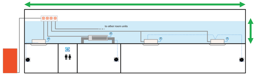
Corridor ceiling plenums often contain VRF piping and branch selector boxes. When evaluating A2L refrigerant safety limits, engineers may need to treat this ceiling volume as the dispersal space for a potential refrigerant leak. Source: Daikin Comfort Technologies North America, Inc.
Some aspects of the current standards are interpreted more conservatively than many engineers would prefer, particularly around releasable charge and evaluated spaces. But as Chris Bellshaw pointed out, the practical approach is to design around the interpretation that the project must comply with.
“The industry may not agree with the current interpretation, but it’s the way the standard is written, and that is how teams have to design today.”
Chris Bellshaw, Vice President of Commercial Strategy and Business Development for Daikin Comfort Technologies North America, Inc.
From a design review standpoint, the biggest coordination issues usually show up in corridor devices and branch-selector placement, not in the room itself.
Mitigation strategies for VRF design
When branch selector boxes are located above corridor ceilings, engineers usually work through a few options:
- Use available volume in the ceiling or adjacent space
In some cases, the local ceiling zone or an adjacent open area provides enough volume to accommodate the releasable charge. - Evaluate connected spaces
If the corridor plenum is connected to adjacent spaces, the effective dispersal volume may extend beyond the local ceiling zone. This depends on having a real, defensible airflow path.
- Use a secondary enclosure with on-demand ventilation
When the available volume is limited, an enclosure around the branch selector box can provide a controlled mitigation approach.
Natural or mechanical ventilation may also be considered, but in practice, these approaches are often less practical than using available volume, connected spaces, or a dedicated enclosure.
Typical VRF System Layout in Multifamily or Hotel Buildings
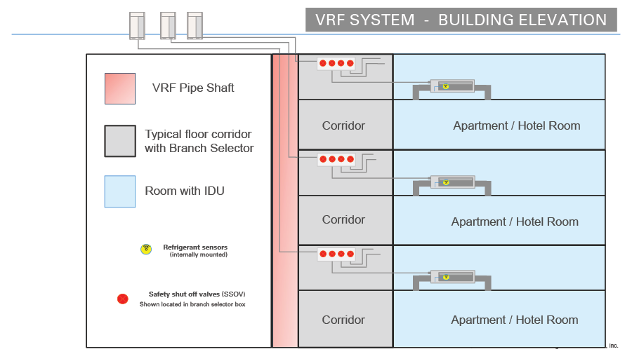
In many multifamily and hotel buildings, branch selector boxes and refrigerant piping are in corridor ceilings adjacent to occupied rooms. These locations influence how refrigerant safety limits are evaluated. Source: Daikin Comfort Technologies North America, Inc.
Changeover and branch selector boxes are often evaluated more conservatively than expected.
“Follow the interpretation the project has to live with, then design around it.”
Chris Bellshaw, Vice President of Commercial Strategy and Business Development for Daikin Comfort Technologies North America, Inc.
That shifts the design question. It is no longer just about corridor volume. It is about which compliance path the layout can support.

Tim Dorman
Innovative Solutions Director
Havtech

Chris Bellshaw
VP of Commercial Strategy & Business Development
Daikin Comfort Technologies