You can meet the sound target and still miss the design goal.
Once silencers, barriers, or enclosures are installed in the air and sound path, they become part of the HVAC system. But, how do you reduce noise without compromising equipment performance?
Effective data center noise control starts with tested silencer and acoustical-panel performance. That tested data is the baseline for predicting results, comparing options, and selecting a solution that meets the sound target without unnecessary cost or guesswork.
The guidance in this article comes from a Havtech-hosted technical session with Mauricio Salinas, P.Eng. and Mike Koupriyanov, P.Eng., of Price Industries Limited. Together, they explain what to evaluate before finalizing the design.
Want to hear the full technical discussion? Watch the on-demand session.
Why Distance Alone May Not Solve Data Center Noise
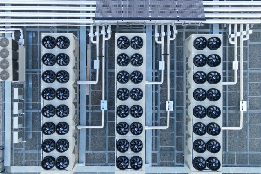
More equipment means more sound, and on a large data center campus; distance alone may not reduce noise enough to meet the project requirement.
For example, 72 chillers rated at about 96 dB each combine to an estimated total sound level of about 115 dB.
Under idealized free-field conditions, that level falls to roughly 71 dB at 500 feet. Nearby buildings, reflective surfaces, and dense equipment layouts can amplify sound.
How Site Conditions Affect Estimated Chiller Sound
|
Environment (72 Chillers at 96 dB each) |
Estimated Level at 500 ft. |
|
Free field (open terrain) |
~71 dB |
|
Some reflective surfaces |
~74-79 dB |
|
Dense mechanical yard / nearby buildings |
~79-84 dB |
|
Highly reverberant courtyard-like setting |
Potentially high locally |
Illustrative estimate based on idealized and reflective site conditions. Actual results require project-specific acoustic analysis. Source: Price Industries example presented by Mauricio Salinas, P.Eng., recreated as an original Havtech table.
“Distance alone is not going to solve your data center noise challenges.”
– Mauricio Salinas, P.Eng.
Three Questions to Ask Before Selecting Acoustical Treatment
Select acoustical treatment only after you understand the sound target, airflow path, and service requirements. A silencer, wall, or enclosure may reduce sound while also adding pressure drop, change airflow, trapping hot air, or limit access if the treatment is not coordinated with the equipment layout.
Before choosing an acoustic treatment, ask:
- What sound target applies? Confirm the required sound level, where it will be measured, and under what operating conditions.
- What happens to airflow? Review pressure drop across the full air path, including air distribution products such as silencers and louvers, along with transitions, screens, and enclosures.
- Will the design preserve service access? Show access panels, removable sections, lifting paths, and service clearances on the drawings. Coordinate structural support before fabrication.
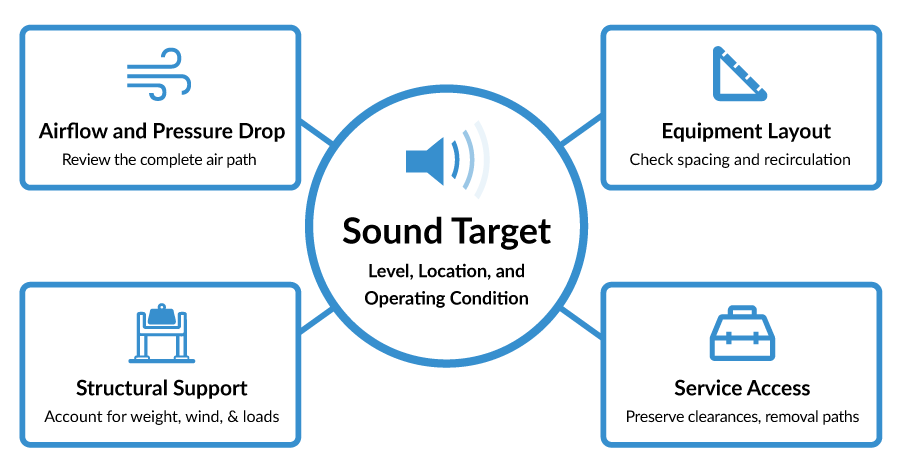
Check these requirements before finalizing the equipment layout or enclosure design. Use the same review for generators and other heat-rejection equipment.
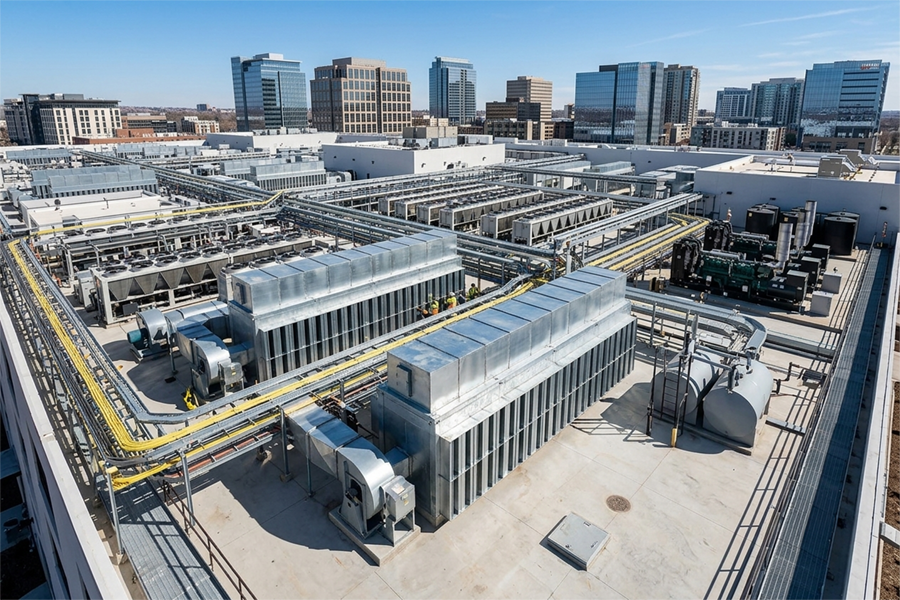
See how Havtech applied this coordinated approach to a custom chiller acoustic enclosure at a library in Reston, Virginia.
How CFD Tests Pressure Drop and Recirculation
Computational fluid dynamics (CFD) does not replace tested acoustic data. Instead, it helps confirm whether the selected acoustic treatment can operate within the equipment’s mechanical limits.
To make the CFD review meaningful, the equipment manufacturer must provide the allowable limits for airflow reduction, pressure drop, intake temperature, and any other performance constraints. Those limits define the operating window within which the acoustical treatment must stay.
CFD tests how the full system behaves after acoustical treatment is added, including airflow, intake temperature, hot-air recirculation, and pressure drop.
The best time to identify an airflow problem is when the design can still be changed. Use CFD to compare options before finalizing the enclosure and equipment layout.
Modeled Results:
Conditions: 109.6°F ambient temperature and 11.2 mph wind speed.
|
Metric |
Without silencers |
With silencers |
|
Hot-air recirculation |
17%–19.9% |
5%–9.3% |
|
Airflow |
Baseline |
About 5% lower |
|
Total pressure difference |
Baseline |
About 0.17 in. w.g. higher |
|
Average chiller intake temperature |
Baseline |
About 2°F–3°F lower |
What the model shows:
In this air-cooled chiller example, the acoustical treatment increased the total system static pressure by about 0.2 in. w.g. and reduced fan airflow by about 5%. At the same time, it reduced self-recirculation and lowered average chiller intake temperature, with no modeled cooling-capacity derate. These results are specific to the modeled equipment, site layout, wind conditions, and treatment design. The same review should be completed against the manufacturer’s allowable limits before finalizing the design.
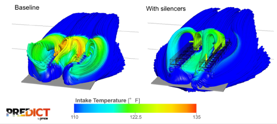
Figure 1. Modeled airflow and intake-temperature patterns for the baseline chiller configuration and the configuration with silencers. These results apply only to the modeled equipment layout and operating conditions. Image credit: Predict by Price, Price Industries.
Verify Sound and Mechanical Performance
Tested performance data for silencers and acoustical panels provide the baseline for acoustic prediction. Price’s acoustical analysis software uses that data to estimate sound levels and compare treatment options, helping the design team choose an effective and cost-conscious solution rather than relying on assumptions.
In the Reston Library example, the acoustical analysis predicted about 55 dBA at five feet. After installation, a Class 1 sound meter measured about 53 dBA at the same distance.
Measure sound at the project-defined location and under the specific operating conditions, then pair the acoustic test with mechanical checks for airflow, pressure drop, intake conditions, recirculation, and service access.
Field results may differ from modeled results due to nearby walls, temporary barriers, future equipment, or installation tolerances. Startup, commissioning, and field verification help catch those differences before they become operating complaints.
Key Takeaways
- Base acoustic selections on tested data. Acoustical analysis tools use tested silencer and panel performance to estimate sound levels, compare options, and support cost-conscious selections.
- Review the full system, not the equipment in isolation. Silencers, barriers, louvers, enclosures, and structural supports can affect airflow, pressure drop, recirculation, access, and equipment performance.
- Set the limits before running CFD. Manufacturer-defined airflow, pressure-drop, and intake-temperature limits give the CFD analysis a clear performance target.
- Verify both sound and mechanical performance after installation. Field checks should confirm sound level, airflow, pressure drop, intake conditions, recirculation, power, and service access.
- Coordinate structural support before manufacturing. Review supports, attachment points, and PE-stamped attachment details before fabrication to confirm the acoustical solution can withstand local live and dead loads.
- Plan for future phases. Future equipment, site changes, and reflective conditions can affect both campus noise levels and airflow performance.
Bring the acoustical and mechanical requirements together early in design. Havtech can review the sound target, equipment limits, treatment design, and field-verification plan for your application.
Review my noise control application
About the Author:
 Steve Clark is Business Development Leader – Air Distribution at Havtech. He has worked in the HVAC industry since 1987 and joined Havtech in 2012. With decades of experience in commercial HVAC applications, Steve also teaches noise control on behalf of Price Industries for Havtech, helping engineers understand acoustical considerations in HVAC system design.
Technical Contributors:
 |
Mauricio Salinas, P. Eng. Mauricio Salinas is Sales and Business Development Manager for Noise Control at Price Industries Limited. He oversees sales and project engineering teams focused on HVAC noise-control applications and brings 14 years of industry experience. His work focuses on acoustical treatment, equipment integration, and structural coordination, while also supporting other Price product lines in developing industry- leading HVAC solutions and products. |
 |
Mike Koupriyanov, P. Eng. Mike Koupriyanov is General Manager of Predict by Price, the computational fluid dynamics division of Price Industries. He has more than 17 years of experience using CFD to solve HVAC challenges and leads analyses involving airflow, heat rejection, recirculation, equipment interactions, and cooling performance. He is also a regular ASHRAE presenter and committee member. |